Solved the diagram represents a: a.pure capacitive Unity power factor causes, advantages, improvements Purely capacitive circuit phasor diagram
Draw the time - and - phasor diagram for a purely inductive circuit
Diagram circuit pure capacitive represents phasor resistive inductive question waveforms Phasor rlc impedance What is resistive circuit? example & diagram
Phasor representation of one phase ac circuit presentation
Circuit capacitive inductive cosAc supply to pure resistor (theory, phasor & waveforms Pure resistive circuit calculation purely phasor resistor supply ac powerPhasor diagram of capacitor in ac circuit.
Phasor diagram resistive pure circuitsPhasor diagram pure capacitive circuit Inductor lagging currentPurely resistive ac circuit.

Power unity factor circuit pure resistive advantages alternating resistor current ac when both
Resistive purely resistorPurely resistive, purely inductive and purely capacitive circuits for jee Find out the phase relationship between voltage and current in a pureAc circuits with resistors, inductors and capacitors.
Ac resistance diagram phasor circuit impedanceAc capacitance inductance phasor diagram circuit inductive capacitive reactance analysis gif physics emo Ac capacitance and capacitive reactance in ac circuitMeaning of purely resistive at beverly eisenbarth blog.

Phasor diagram for pure resistive circuits
Why power in pure inductive and pure capacitive circuit is zero?Ac circuit containing only an inductor Purely resistive, purely inductive and purely capacitive circuits for jeePhasor diagram for pure resistive circuits.
Phasor diagram of pure resistive circuitAc resistance and impedance in an ac circuit Instantaneous waveform voltage electricalworkbook waveforms resistor purely resistive[answered] the phasor diagram shown below represents cot purely.

Rlc series circuit
Capacitors lagging impedance inductor inductors phasor inductive ohms circuit ohm expand generalizeAc through pure resistor Draw the timeAc circuit containing pure resistor.
What is a pure inductive circuit?Circuit inductive pure diagram purely phasor waveform draw voltage alternating applied What is a power triangle? active, reactive & apparent powerPurely capacitive circuit phasor diagram.

Ac supply to pure resistor (theory, phasor & waveforms
Circuit inductor phasor containing current inductive alternating reactanceWhat is a purely resistive circuit? circuit diagram, phasor diagram .
.


Phasor Diagram for Pure Resistive Circuits | Electrical Engineeri

AC Capacitance and Capacitive Reactance in AC Circuit

Phasor Diagram Pure Capacitive Circuit

Find out the phase relationship between voltage and current in a pure
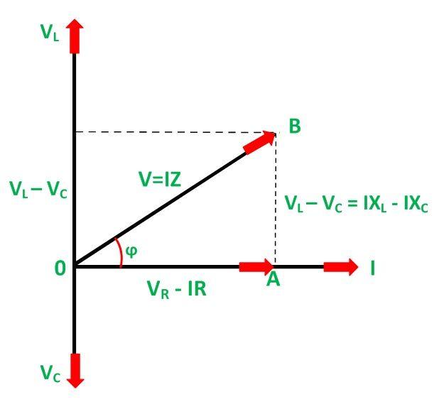
RLC Series Circuit - electrical and electronics technology degree

Draw the time - and - phasor diagram for a purely inductive circuit

Purely Resistive AC Circuit | Expression of Current & Power, Waveform
